 |
Ohio Automation, Inc. |
|
Mining Ventilation Software and More |
||
Engineering Software since 1985 |
||
| Home | AboutUs | MineSimU | MineVent | MineFire | MineWater | Downloads | ContactUs | Support | Services | Prices | Customers |
ICAMPS - Integrated Computer Aided Mine Planning Software |
||||||
Call 740-596-1023 Today! |
||||||
MineWater Pumping System Simulation Analysis |
||||||
The MineWater program is designed to analyze the flow of mine discharges through complex piping networks. The program can be used to evaluate the effects of alternate pumps, pipe sizes and flow routings in existing or proposed discharge systems. The program generates a static solution showing flow rates through pipes, and pressures at pipe junctions (calculated using the Hazen-Williams headloss formula) for a fixed input condition. If a duration is spefified the program will generate simulations of a system over time, allowing for control sequences such as the starting and/or stopping of pumps under specified conditions or at specific times. The program interface is very similar to that of Ohio Automation's MineVent, as is the data output, and should be generally familiar to users of that program. The key user tasks in constructing a MineWater network are 1) digitizing nodes, 2) drawing and describing branches, and 3) describing the operating characteristics of existing and/or proposed pumps. The program stores up to 12 user pre-defined pipe classifications which are assigned separate layers for display purposes; for user convenience, it is best to 4) configure the "typical" pipes found in the system (categorized at the user's discretion by material, size, condition and/or roughness coefficient) before starting to construct the network model. |
||||||
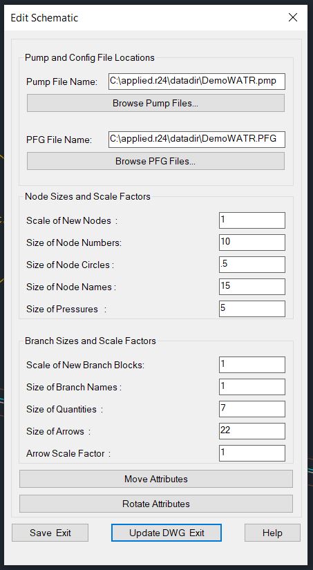
| Edit Schematic | ||||||
 |
||||||
| Edit Schematic allows you to set the default pump and configure branches file as well as change the sizes of all MineWater entities on the drawing and move and rotate node numbers, quantities etc... | ||||||
| Configure Branches | ||||||
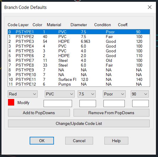
The hydraulic characteristics of "typical" branches can be described in "Branch Menu/Configure Branches..." for ease in defining new branches. The user has a great deal of flexibility in assigning how branches are to be displayed; the only limitation is the 12 available layers. He/she can group all pipes of a certain diameter (for example) in one code/layer, or further subdivide the system by assigning pipes of different diameters and different materials to separate codes/layers. One (or more) code/layer can be reserved for displaying the location of pumps, or other branches of particular interest. Initially the configuration list is populated with an arbitrary range of materials, diameters, conditions and coefficients, but the user should re-organize this list to best suit his/her needs. To change a code, highlight it and re-assign characteristics using the selection boxes, then "Change/Update List" before moving to another code or exiting the dialog with "OK". The appropriate roughness coefficient will depend primarily on material and condition, and can be found in a standard hydraulics handbook or obtained from the manufacturer. Since this coefficient can be readily changed when "Defining" or "Modifying" a branch, it is recommended that this NOT be the basis for assigning the (limited!) codes. |
||||||
Configure Branches dialog interface |
||||||
| Nodes | ||||||
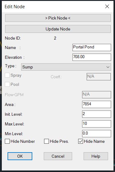
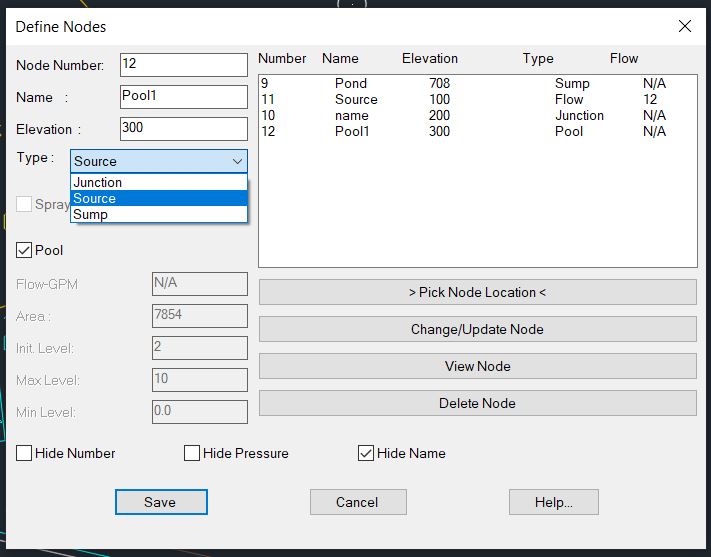
Digitizing Nodes [Node Menu/Define New Nodes...] - As in MineVent, nodes are placed on the mine map wherever there is a junction of two or more branches (pipes) or where branch characteristics change (e.g. - pipe size or pipe resistance). In addition, nodes are placed where a branch discharges (e.g. - intermediate sumps) or begins (e.g. - at a measured inflow or unlimited source). Unlike MineVent, there are three distinct node "types" used in MineWater, but they are all activated through the same dialog box and their application is transparent to the user. Node Type "Junction" is used where pipes join or change characteristics. This is the default option when the "Define New Nodes..." dialog box is opened. Each new node is assigned a number (by default, the next higher unused node number, but changeable by the user). Each node can also be given a "Name" by the user. The program expects an elevation for each node, which is used in the pressure calculation. (This is not critical for Junctions, since the flow through a system is dependent primarily upon system inlet and outlet elevations, energy inputs and line losses, but it is useful in conjunction with actual pressure readings taken in the system for model validation). Node Type "Source" is used to represent a known inflow to the system (e.g. - a scavenger pump pick-up point, or a gravity inflow to a sump). Elevation here is important, especially for a pump pick-up, and a measured or estimated flow rate is required. If the "Source" is essentially an unlimited body of water, the "Source" is designated as a "Pool" (by checking the "Pool" box), and only the pool elevation is needed. Node Type "Sump" is basically a storage tank into which water may flow or be pumped, and from which water is withdrawn by a pump. For a sump, the program requires an elevation (at the bottom of the sump), an "area" (presently assumed to be uniform with depth -- use an average), a "min[imum] level" (the lowest point to which the sump can be drawn, as measured ABOVE the sump elevation), a "max[imum] level" (the highest level, again ABOVE the sump elevation, to which the sump can fill), and an "init[ial] level" (Note this value will be critical for simulations with "Controls"; at present any value between the "min. level" and the "max. level" is acceptable.) |
||||||
Define New Nodes Dialog Box |
||||||
 |
||||||
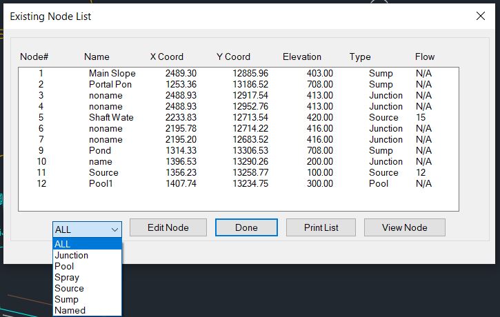
| List Nodes Dialog Box | ||||||
 |
||||||
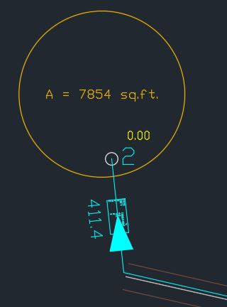
| Pipe connected to a Sump Node Schematic | ||||||
 |
||||||
| Edit Node shows the properties of Node 2 on the schematic. | ||||||
| Branches | ||||||
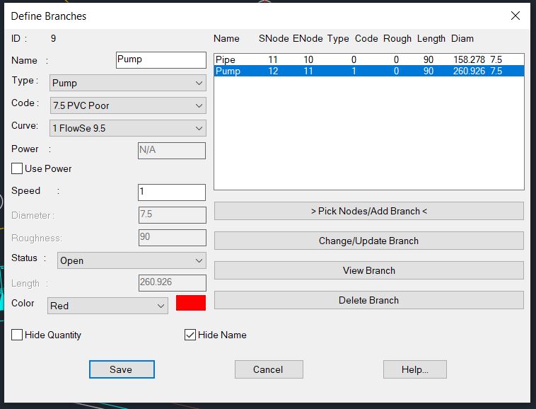
Defining Branches [Branch Menu/Define New Branches] - As in MineVent, branches are drawn on the mine map between nodes and should approximate the actual pipeline route for greatest accuracy. Two key factors here are the branch "Type" (pipe or pump) and "Status". The user also selects a "Code" from the pre-defined configuration list, which automatically inserts the appropriate "Diameter" and "Roughness". (The user can change these default values for any individual pipe, or the color in which it will be displayed, but not the display layer -- so select the "Code" thoughtfully!) Branch Type "Pipe" is used to describe pipe characteristics. The "Length" is automatically calculated as the branch is drawn (but can be changed by the user). The "Size" is entered as diameter in inches and the "Roughness" is the "C-factor" for the pipe -- automatically entered as pre-defined in "Branch Menu/Configure Branches...". The "Status" of a pipe is important; it can be "Open" (the default) or "Closed" (valved off, allowing a connection to be described in the system without actually being used), or it can be a "C[heck] V[alve]" (allowing flow only in the direction in which the pipe was originally drawn). Note that if an unused branch contains a check valve, it might better be described as two branches in series - one "Closed" and one "CV" - so that the "Closed" branch can later be "Opened" and still controlled by the "CV". Branch Type "Pump" is used to designate pump locations. As with pipes, the "Pump" is drawn between two nodes -- but the "Length" is disregarded. The "Status" of a pump should be either "Open" (running - the default) or "Closed" (not running). The appropriate pump curve number can be selected in "Curve". If the pump is a constant-volume (e.g. - piston type) unit, the "Use Power" box should be checked and the effective horsepower (after drive losses) should be entered. If the pump is variable speed, to represent its operation in MineWater, the appropriate pump curve number is selected, then the speed relative to the base curve is entered in the "Speed" box (i.e. - if the pump is running at twice "normal" speed, enter Speed: 2,; if half speed, 0.5). |
||||||
Define Branch Dialog Box |
||||||
| Modify Branch Parameters | ||||||
| Modify Branch Parameters is a quick way to select a branch in the drawing and change anything associated with the branch. | ||||||
 |
||||||
| Advanced List Branches Full View (Increase browser size to make readable) | ||||||
| Advanced List Branches is a very powerful way to modify all the branch data in the drawing or a selection, export to a spreadsheet file, find and delete branches and view timesteps if applicable. All columns have the ability to sort by the parameter. The light green background lets you know what can be edited based on branch type, Use Power, Curve or any other information. If it is light green it cannot be edited unless you change the branch type etc.. | ||||||
 |
||||||
| Advanced List Branches Scaled Down View | ||||||
 |
||||||
| Pump Curves | ||||||
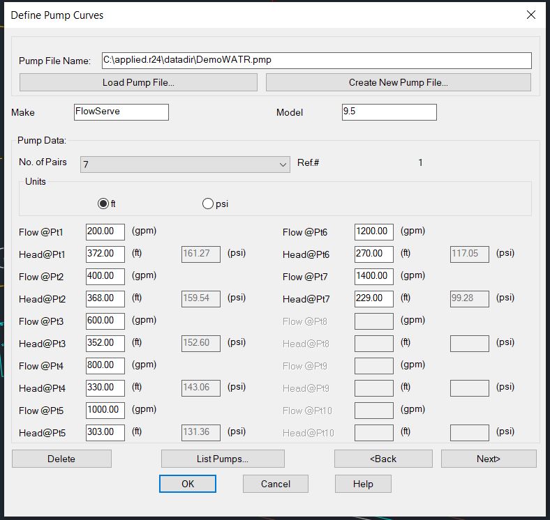
| Defining pump curves is accomplished through "Define/Edit Pumps..." in either the "Node" or "Branch" menu. The operation is essentially the same as defining fans in MineVent. Data points should be entered in descending order of Head, expressed in feet. If an error message occurs when the program is "Run", try adjusting or eliminating points on the indicated pump curve (If the curve as described is actually linear, the program is unable to handle it). Note that entering a meaningful make and model is very handy when it comes to assigning the right curve number to a "Pump" branch! |
||||||
Pump Curves Dialog Box |
||||||
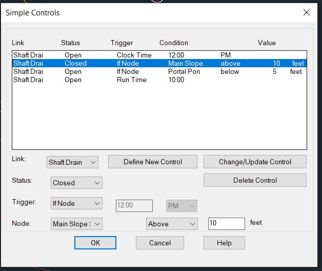
| Simple Controls | ||||||
| Use the simple controls to control changes that occur while the program is running in real-time such as opening and closing a branch if a condition is met. | ||||||
 |
||||||
| Set Controls/Simple Controls | ||||||
| Running MineWater | ||||||
| To run the model, "Run MineWater..." can be selected from either the Node or Branch menu, or using the "hot button" in the MineWater toolbar to the left of the screen. This brings up a dialog with potential options. The duration is how long the system will run and checking the Use Controls uses the controls set in Simple Controls above. | ||||||
Creating Input fle and Running MineWater |
||||||
 |
||||||
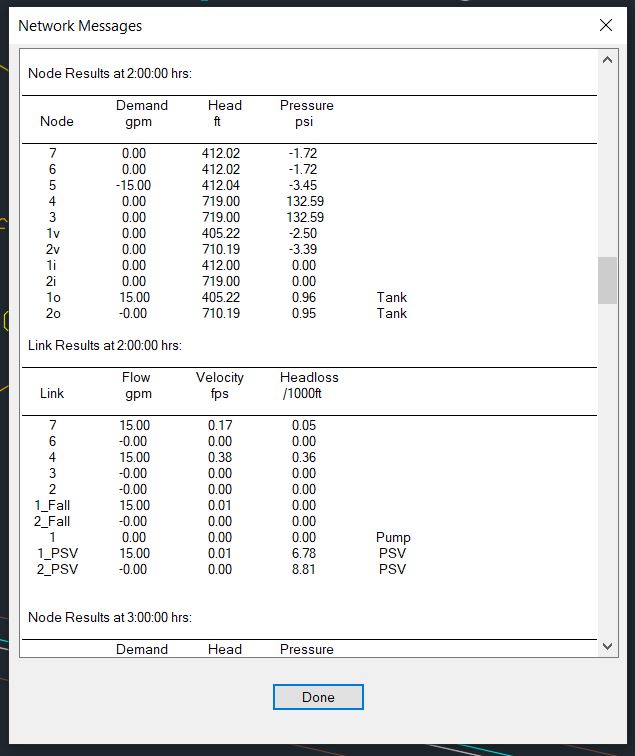
| Partial screenshot of Network Messages | ||||||
 |
||||||
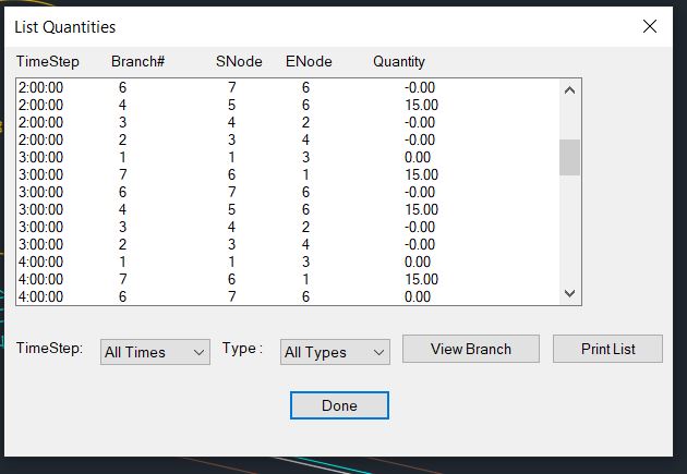
| List Quantities shows the quantities in gpm for the timesteps. | ||||||
 |
||||||
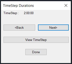
| You can cycle through the timesteps and view the quantities and pressures on the schematic for each timestep. | ||||||
Summary of Features for MineWater
|
||||||

© 2000 - 2007 Ohio Automation All Rights Reserved |